

As AI-driven data centers deploy hundreds of medium-voltage transformers to feed megawatt-scale compute clusters, the electrical protection schemes guarding those assets have moved from a substation-engineering specialty to mission-critical infrastructure design. This article surveys the full transformer protection stack, then focuses on the device at its core: the differential relay.
Part 1: The Data Center Fleet Problem & AI Power Infrastructure
A power transformer failure in a conventional utility substation is a serious but manageable event—typically involving one unit, a planned outage, and a replacement timeline measured in months. However, the same failure inside a hyperscale data center represents a completely different order of magnitude. It drops a hall segment instantly, interrupts artificial intelligence (AI) training runs that represent weeks of compute investment, and requires replacing equipment with lead times that now routinely stretch from two to four years.
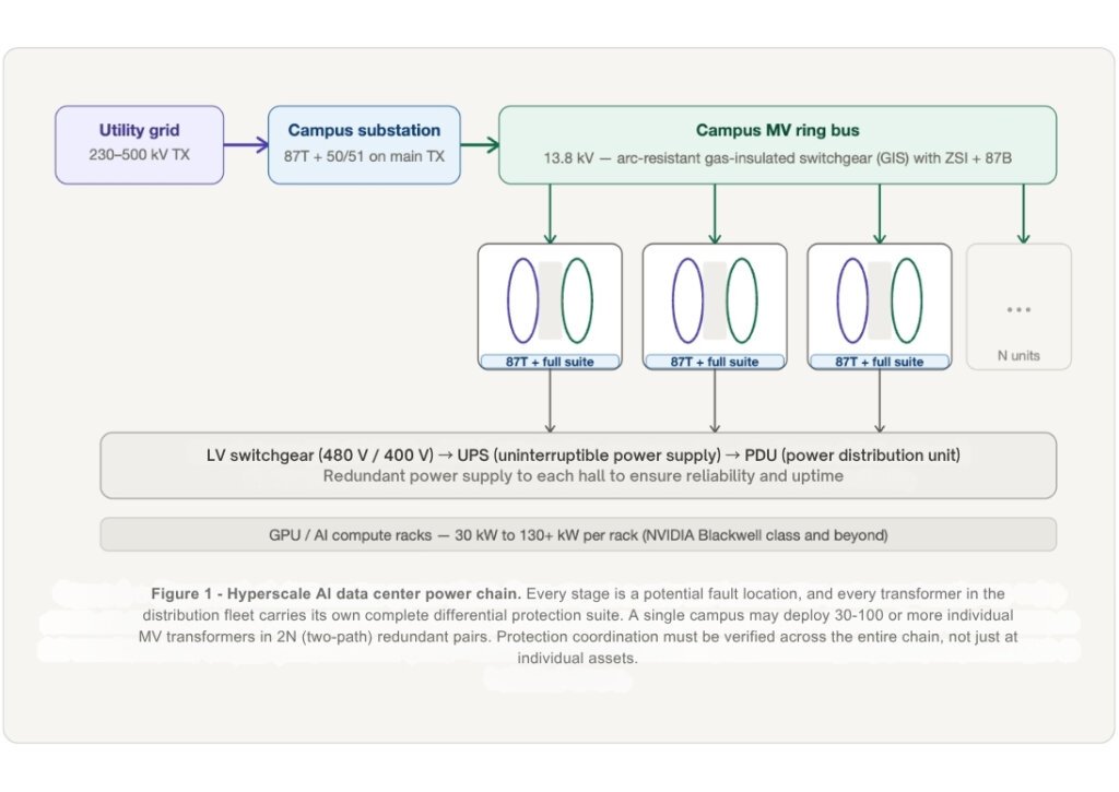
The sheer scale of AI deployment makes this risk systemic. A single hyperscale AI campus today draws 150 to 500 MW of continuous load—comparable to a small city. That power arrives through a cascade of transformers: a large utility-grade unit at the substation stepping transmission voltage down to a campus medium-voltage (MV) ring, followed by dozens to hundreds of individual MV distribution transformers feeding individual server halls. Each of those distribution units is a potential single point of failure if unprotected.

This is the business case for transformer protection and substation design engineering done right: not just preventing equipment damage, but preserving availability, maintaining uptime commitments, and protecting the multi-hundred-million-dollar compute assets that depend on uninterrupted power quality.
Stakes Specific to the Data Center Operator
Several characteristics of data center power infrastructure make the differential relay particularly critical in this context:
- Dense, parallel deployment: Unlike traditional utility substation design with one or two major transformers, a campus switchgear line-up may energise 30-100 MV transformers over its lifetime. Each energisation event is an inrush challenge for the 87T relay.
- AI load profiles are non-sinusoidal: GPU server power supplies generate significant harmonic load current (3rd, 5th, 7th harmonics). These harmonics distort the CT secondary waveforms and can produce low-level differential currents during normal operation.
- Uptime = revenue: A missed trip (relay fails to operate on a real internal fault) is catastrophic. A false trip is equally costly: it drops the entire hall segment, triggering failover and interrupting live AI training clusters.
- Speed matters: The differential relay’s sub-2-cycle trip time limits the energy dissipated at a fault point. On a stiff MV bus, fault currents can reach tens of thousands of amperes. The faster the fault is cleared, the lower the cumulative damage to the switchgear bus.
- Selectivity must be maintained: With many parallel transformers on a shared MV bus, it is critical that a fault in one transformer trips only that unit’s breakers—not the upstream ring.
Part 2: The Complete Protection Picture
Utility-grade transformer protection is not a single relay—it is a coordinated defense-in-depth strategy. Each layer addresses a specific failure mode, a specific fault location, and a specific response speed.
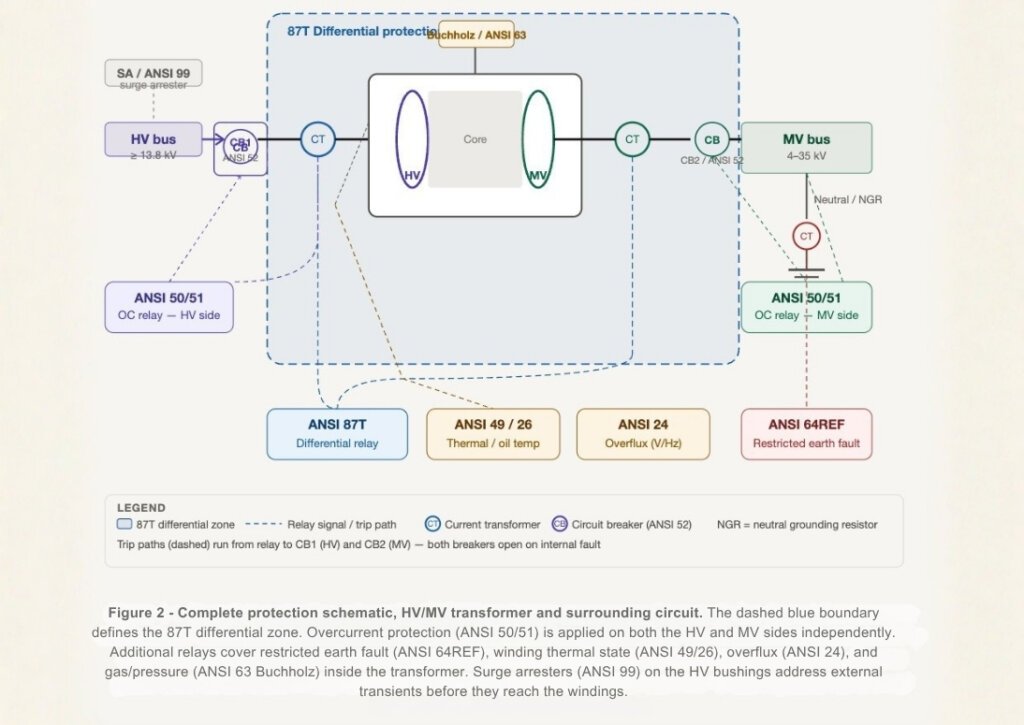
To protect these assets, facility engineers must coordinate devices across three zones: the HV primary circuit, the transformer itself, and the MV secondary circuit.
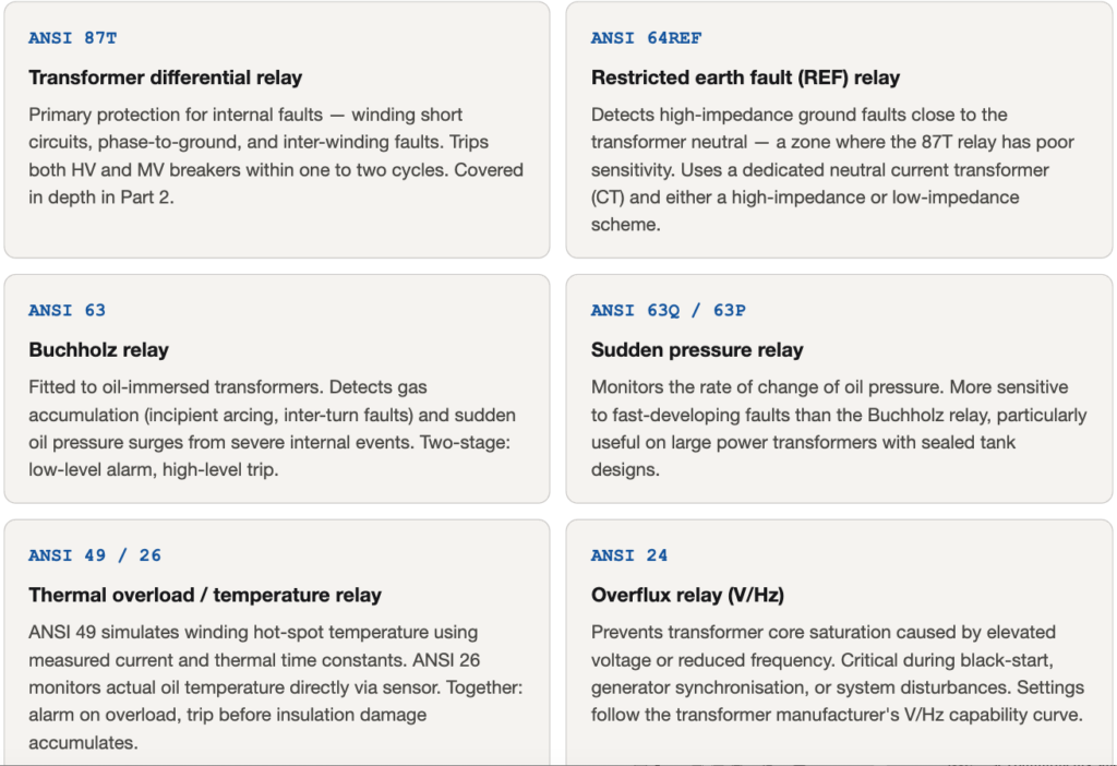
Transformer-Mounted Protection
The most critical relays address failure modes originating inside or directly at the transformer. These devices form the core of the protection stack:
Circuit Protection (HV and MV)
Upstream and downstream devices provide essential backup and selectivity to complement the transformer-mounted relays:
- Surge Arresters (ANSI 99): Clamps lightning impulses and switching transients at the HV bushings before they damage winding insulation.
- Instantaneous/Time Overcurrent (ANSI 50/51): Applied independently on both the HV and MV sides. The instantaneous element clears massive faults quickly, while the time-overcurrent element provides time-graded backup for through-faults.
Secondary Switchgear Defences: Data centers frequently utilize Arc Flash Detection (ARCD) relays for millisecond bus fault clearance, and Zone-Selective Interlocking (ZSI) to ensure secondary main breakers wait for downstream feeder relays to clear localized faults.
Part 3: Engineering the Differential Relay & Commissioning
At the center of this massive stack is the most precisely engineered device of all: the Transformer Differential Relay (ANSI 87T).
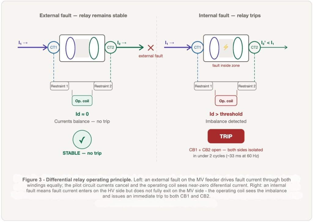
A transformer doesn’t consume current—it transforms it. The differential relay utilizes Kirchhoff’s current law as a fault detector. It continuously compares the current entering the high-voltage side against the current leaving the medium-voltage side (scaled by the turns ratio). Under normal load or external faults, these quantities balance. If a fault occurs inside the transformer, current leaks. That imbalance—the differential current—forces the relay to trip both circuit breakers simultaneously in roughly 33 milliseconds (at 60 Hz).
The Engineering Reality: Why a Simple Scheme Fails
While simple in theory, several normal electrical conditions create imbalances that would falsely trigger a basic relay:
- Magnetizing Inrush: When energized, the core “charges up,” drawing a transient current 8-12 times the rated load on the HV side with no corresponding MV output.
- CT Saturation: During heavy external faults, massive currents can push one CT into magnetic saturation, creating a spurious differential signal.
- Vector Group Phase Shifts: Utility transformers (like Dyn11) introduce a 30-degree phase shift between HV and MV currents that must be compensated.
The Solution: The Percentage Relay and Harmonic Restraint
To survive these anomalies, modern Intelligent Electronic Devices (IEDs) utilize a percentage differential characteristic (also called a biased relay). The relay adds restraining coils fed by the “through-current”. It only trips when the differential current exceeds a specific percentage of that restraint. This allows the relay to remain highly sensitive at low loads, while a dual-slope characteristic increases the required trip threshold during high through-currents when CT saturation is likely.
To handle inrush, the relay utilizes harmonic blocking. Because inrush current is uniquely rich in the second harmonic (30-70% of the fundamental frequency), the relay measures this via real-time signal processing. If the second harmonic exceeds a threshold (typically 15-20%), the relay restrains its trip output, knowing the event is inrush rather than a fault.
The Cost of Compressed Commissioning
Commissioning is where the gap between a protection system that is installed and one that will actually perform closes — or doesn’t. In data center construction, it is also the phase most consistently compressed under schedule pressure. The consequences of that compression are not always visible at energization. They surface later, under fault conditions, when the relay is called upon to perform and the assumptions made during commissioning are tested for the first time against real electrical conditions.
For large MV transformer fleets, relay settings files are generated once for a standard unit and deployed across all matching units. This creates efficiency and replication risk in equal measure. Version control, functional verification, and periodic re-testing after firmware upgrades are not optional practices in a fleet protection environment — they are the difference between a settings error affecting one unit and one affecting forty.
Closing Thoughts
Transformer protection for utility-grade MV-HV equipment is a layered, interdependent system. Faults must be cleared selectively and quickly—with minimum impact on uptime and maximum protection for equipment that can take years to replace.
At the centre of that system is the percentage differential relay (ANSI 87T): the fastest, most selective, and most precisely engineered device in the stack. In the context of AI hyperscale design, where power system reliability directly enables or interrupts compute availability, the differential relay has moved from a traditional substation design specialty to a front-line infrastructure concern. Getting it right—across every unit in a fleet of dozens or hundreds of transformers — is the operationally decisive work that determines whether the infrastructure performs to its design intent.
Ready to Secure Your Hyperscale Power Infrastructure? Contact Our Engineering Team.
References & Industry Standards
- IEEE C37.91-2008: Guide for Protective Relay Applications to Power Transformers
- IEEE C37.2-2008: Standard for Electrical Power System Device Function Numbers (ANSI Codes)
- IEC 60255-151: Measuring Relays and Protection Equipment
- IEC 61850-8-1 / 9-2: GOOSE Messaging and Sampled Values for Protection IEDs
- QY Research: Transformers for Data Centers Global Market Share and Ranking 2025-2031 (2025)