
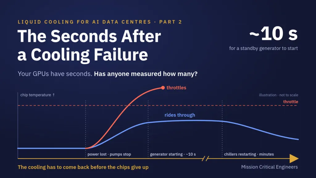
When a coolant pump stops, your GPUs have seconds. Not the minutes an air-cooled room used to give you.
Every liquid-cooled design says it is redundant. What matters is whether it keeps the chips cool through the first minutes of a failure, at full heat, and whether anyone has proven it.
In the first post of this series we said the time to react to a liquid cooling failure drops to seconds in a liquid-cooled AI data centre. This is why that is the question that matters most. In an air-cooled room, losing a cooling unit gave the operators time to respond. With direct-to-chip liquid cooling, the heat leaves each processor through the coolant. Stop the flow, and the chip’s heat has almost nowhere to go.
Inside a Direct-to-Chip Cooling Loop
A direct-to-chip system is a chain, and every link carries heat all the time.
Air cooling had slack in every link. In this chain, a pause anywhere reaches the chip within seconds.
What Is at Stake
A GPU that runs out of cooling protects itself. It throttles first, and if the heat keeps rising, it shuts down. For an AI training job that is more than a slow hour: the run falls back to its last checkpoint, and the work done since then is lost across every GPU in the job. Each overheating event also puts the hardware through another heat cycle, and repeated cycling shortens its life.
Liquid cooling also concentrates the risk. Racks share pumps, headers and controls, so one failure mode nobody proved can take down a whole row, or a whole hall, at once. And the trigger is rarely exotic: a utility dip, a tripped breaker, a standby pump that does not start.
Why It Goes Wrong
1 The buffer is gone
An air-cooled hall had thermal mass: a room full of cool air and the building around it bought minutes. A cold-plate loop’s only buffer is the coolant in it, and at the chip there is very little.
2 The flow stops with the power
When the utility drops, everything that keeps coolant moving and under control has to keep running through the transfer to standby power. A standby generator takes about ten seconds to start. If the flow pauses for that gap, the chips are already past their limit.
3 The plant takes minutes to come back
A power event also stops the chillers, and a chiller takes minutes to restart. The racks keep making heat the whole time, so the loop has to carry it until the plant returns.
4 Failover was tested cold
A pump or CDU switchover tested with no heat on the loop proves that the valves move and the standby pump starts. It does not prove the racks stay below throttling while it happens.
5 Redundancy that is not redundant
Two CDUs that share one header, one controller or one power path are N+1 on the drawings and a single point of failure in fact.
Each of these gaps is easy to miss, because on paper the design passes. The drawings show backed-up power, the controls description says N+1, and the switchover was signed off. The gap only shows when the hall loses power at full heat, the one condition most projects never create before the servers arrive.
One Power Loss, Two Designs
How many seconds the chips have depends on the chips, the cold plates, how much coolant is in the loop and how hard the racks are working. No public standard gives one number for it. That is exactly why it has to be measured on your system, not assumed.
Three Questions for Your Team
- Does coolant keep moving to every rack through a utility power loss?
- Was ride-through shown with full heat on the loop, or with the loop cold?
- How many seconds does your design give the chips, and who measured it?
If any answer is “we assume so”, that is where the risk sits.
In the next post: who owns the loop between the servers and the building?
Prove It Rides Through, Before the First AI Rack Depends on It
At MCE, our commissioning starts with a design review. It finds single points of failure, commissionability gaps and controls that cannot be verified while they are still cheap to fix on paper.
Our commissioning testing proves, at full heat load, that the hall rides through every failure it is designed for, with every rack below throttling.
Planning or building a liquid-cooled hall? We would be glad to talk through what your design needs to prove.
Have a data centre project in planning?
Tell us about your project, and we will come back to you.
Send your project requestRelated Posts
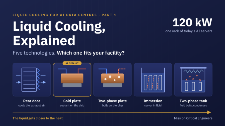
Liquid Cooling, Explained: Five Technologies and Where Each Fits
Five liquid cooling technologies for AI data centres: rear doors, single- and two-phase cold plates, single- and two-phase immersion. What…
Read More »
Load Bank Testing in Data Centre Commissioning: Six Problems We See on Almost Every Project
Six load bank testing problems that derail data centre commissioning — generator tests that prove nothing, cooling validation that misses…
Read More »
The Commissioning Illusion: What Your Vendor Start-Up Report Doesn’t Tell You
Vendor start-up proves each piece of equipment in isolation. An independent commissioning authority proves the facility works as one integrated…
Read More »